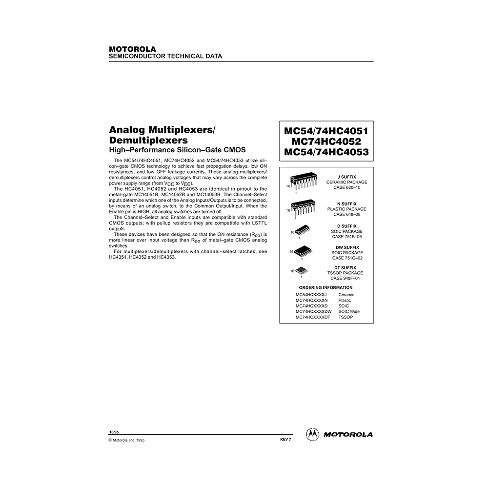
MC54HC4051 Motorola Analog Multiplexer/Demultiplexer Data Sheet
Download PDF datasheet for Motorola Semiconductor MC54HC4051 High-Performance Silicon-Gate CMOS Analog Multiplexer/Demultiplexer (EN) 15 pages Rev.7 1995 zip
Description
This PDF datasheet is for the Motorola Semiconductor MC54HC4051 Multiplexer/Demultiplexer.
About the Item
Motorola Semiconductor MC54HC4051 High-Performance Silicon-Gate CMOS Analog Multiplexer/Demultiplexer
The MC54HC4051 utilize silicon-gate CMOS technology to achieve fast propagation delays, low ON resistances, and low OFF leakage currents. These analog multiplexers/demultiplexers control analog voltages that may vary across the complete power supply range (from VCC to VEE).
The HC4051 is identical in pinout to the metal-gate MC14051B. The Channel-Select inputs determine which one of the Analog Inputs/Outputs is to be connected, by means of an analog switch, to the Common Output/Input. When the Enable pin is HIGH, all analog switches are turned off.
The Channel-Select and Enable inputs are compatible with standard CMOS outputs; with pullup resistors they are compatible with LSTTL outputs.
These devices have been designed so that the ON resistance (Ron) is more linear over input voltage than Ron of metal-gate CMOS analog switches.
(PDF) DATASHEET (ENGLISH)
SUMMARY OF CONTENTS
– Ordering Information
– Logic Diagram
– Function Table
– MC54HC4051 Pinout
– Maximum Ratings
– Maximum Positive DC Supply voltage
– Maximum Negative DC Supply voltage
– Maximum Analog Input Voltage
– Maximum Digital Input Voltage
– Power Dissipation
– Lead Temperature
– Recommended Operating Conditions
– DC Characteristics – Digital Section
– DC Characteristics – Analog Section
– AC Characteristics
– Additional Application Characteristics
– Applications Information
Figure 1. Typical On Resistance
Figure 2. On Resistance Test Set-Up
Figure 3. Maximum Off Channel Leakage Current, Any One Channel, Test Set-Up
Figure 4. Maximum Off Channel Leakage Current, Common Channel, Test Set-Up
Figure 5. Maximum On Channel Leakage Current, Channel to Channel, Test Set-Up
Figure 6. Maximum On Channel Bandwidth, Test Set-Up
Figure 7. Off Channel Feedthrough Isolation, Test Set-Up
Figure 8. Feedthrough Noise, Channel Select to Common Out, Test Set-Up
Figure 9. Propagation Delays, Channel Select to Analog Out
Figure 10. Propagation Delays, Analog In to Analog Out
Figure 11. Propagation Delays, Enable to Analog Out
Figure 12. Crosstalk Between Any Two Switches, Test Set-Up
Figure 13. Power Dissipation Capacitance, Test Set-Up
Figure 14. Total Harmonic Distortion, Test Set-Up. Plot, Harmonic Distortion.
Figure 15. Application Example
Figure 16. External Germanium or Schottky Clipping Diodes
Figure 17. Interfacing LSTTL/NMOS to CMOS Inputs
Figure 18. Function Diagram
Figure 19. Function Diagram
Figure 20. Function Diagram
Why download the Datasheet?
This datasheet provides all the information from Motorola Semiconductor about the MC54HC4051 Multiplexer/Demultiplexer, as detailed in the table of contents. Reading it completely will address most questions you might have. You can download and save it for offline use, including viewing it on your device or printing it for your convenience if you prefer a paper version.
How to download the Datasheet?
Download it by clicking the button below
Helped you out?
Glad to hear that. It would be awesome if you could . . .


