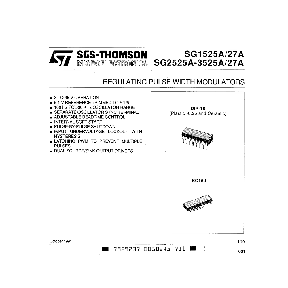
SG3527A ST Regulating Pulse Width Modulator Data Sheet
Download PDF datasheet for STMicroelectronics SG3527A Regulating Pulse Width Modulator (EN) 10 pages 1991 zip
Description
This PDF datasheet is for the ST SG3527A Pulse Width Modulator.
About the Item
ST SG3527A Regulating Pulse Width Modulator
This series of pulse width modulator integrated circuits are designed to offer improved performance and lowered external parts count when used in designing all types of switching power supplies. The on-chip + 5.1 V reference is trimmed to +/- 1 % and the input common-mode range of the error amplifier includes the reference voltage eliminating external resistors. A sync input to the oscillator allows multiple units to be slaved or a single unit to be synchronized to an external system clock. A single resistor between the Ct and the discharge terminals provide a wide range of dead time adjustment.
These devices also feature built-in softstart circuitry with only an external timing capacitor required. A shutdown terminal controls both the softstart circuity and the output stages, providing instantaneous turn off through the PWM latch with pulsed shutdown, as well as soft-start recycle with longer shutdown commands. These functions are also controlled by an undervoltage lockout which keeps the outputs off and the soft-start capacitor discharged for sub-normal input voltages. This lockout circuitry includes approximately 500 mV of hysteresis for jitter-free operation. Another feature of these PWM circuits is a latch following the comparator.
Once a PWM pulses has been terminated for any reason, the outputs will remain off for the duration of the period. The latch is reset with each clock pulse. The output stages are totem-pole designs capable of sourcing or sinking in excess of 200 mA.
(PDF) DATASHEET (ENGLISH)
SUMMARY OF CONTENTS
CONNECTION DIAGRAM AND ORDERING NUMBERS
SG3527A PINOUT
ABSOLUTE MAXIMUM RATINGS
THERMAL DATA
BLOCK DIAGRAM
ELECTRICAL CHARACTERISTICS
– Reference Section
– Oscillator Section
– Error Amplifier Section
– PWM Comparator
– Shutdown Section
– Output Drivers
– Total Standby Current
TEST CIRCUIT
RECOMMENDED OPERATING CONDITIONS
PRINCIPLES OF OPERATION
Why download the Datasheet?
This datasheet provides all the information from ST about the SG3527A Pulse Width Modulator, as detailed in the table of contents. Reading it completely will address most questions you might have. You can download and save it for offline use, including viewing it on your device or printing it for your convenience if you prefer a paper version.
How to download the Datasheet?
Download it by clicking the button below
Helped you out?
Glad to hear that. It would be awesome if you could . . .


